RGB LED Scooter
In this tutorial, you'll be making a scooter with RGB LED Underglow sensitive to the scooter's speed. This project uses the Digital Hall Sensor Wireling and a strand of RGB LEDs.
Materials
Hardware:
- Micro USB Cable
- TinyDuino & USB TinyShield
- Wireling Adapter TinyShield
- 290mAh LiPo Battery
- LEDs:
- RGB LED Wireling (no soldering, but requires some tape and programming!)
- Light Strip & 0.1" Breakout Wireling (this option requires some soldering, so you will also need some Wire and Basic Soldering Equipment!)
- Digital Hall Sensor Wireling
- Wireling Cables
Software:
- Arduino IDE
- RGB LED Hall Sensor Arduino Sketch
- FastLED Arduino library
- (Optional) SVG file for acrylic hardware enclosures:
Extras:
- A Scooter or something you have wheels on
- Electrical Tape (or something similar)
Note:
- When I built this project with a TinyDuino, a Proto Board TinyShield was used to short the Hall Sensor Wireling's input to an interrupt pin on the TinyDuino. The code "as is" will not work with a TinyZero but could be modified for compatibility with just a few changes to the interrupt setup.
- The Proto Board and interrupt short would not be needed with a TinyZero, as the pins to the Wireling connectors are already connected to interrupt pins for that processor.
Step 1: Assembly (Hardware)
TinyDuino:
1. Solder wires to short the following connections on the Proto Board TinyShield
A(hallPortNumber) to Pin 8 (where hallPortNumber is the number on the Wireling Adapter TinyShield where the Hall Sensor Wireling is plugged into).
NOTE: do not use port 0 for this, as it will mess up the uploading process if connected to the processor during the upload
2. If using RGB LED light strip, solder RGB LED strip to GND, 3V3, and INT on the 0.1" Breakout Wireling.
3. Stack TinyDuino, USB TinyShield, TinyShield Proto Board, Wireling Adapter TinyShield
4. Plug RGB LED Wirelings (or LED strip) into Port 0 on the Wireling Adapter TinyShield
5. Plug Hall Effect Sensor (D) Wireling into Port 1 on the Wireling Adapter TinyShield
6. Upload code and test that the lights respond to the magnet, by waving the magnet close to the Hall Effect Wireling. (Pass it by the sensor multiple times)
7. Mount to scooter.
- In order to activate the Hall Sensor, you need to put the magnet on your scooter wheel in a place that it will interact with the Hall Sensor Wireling. I taped the magnet to the wheel and mounted the Hall Sensor in place with some acrylic and sticky foam.
- Everything else is secured closeby in an acrylic encasing with the wires arranged so that there is no possible interference with the wheels. (More details in Step 3)

Step 2: Software (Setup)
Upload the following code to the TinyDuino. Be sure to select:
- Board: "Arduino Pro or Pro Mini"
- Build Option: ATmega328P (3.3V, 8 MHz)
Step 3: The Code!
Click here to download the code .zip file if you haven't done so already!
The following changes are needed for accurate speeds:
- Change wheelDiameter (line 33) to the diameter of the wheel with the magnet in millimeters.
- Change NUM_LEDS (line 67) to the number of RGB LEDs in your strip.
Changing Colors:
You can see all of the Predefined RGB colors in the header file pixeltypes.h starting at line 594: https://github.com/FastLED/FastLED/blob/master/pixeltypes.h
There are a LOT of colors. You can use these colors to customize your Audio Visualizer.
Step 3: Securing Hardware
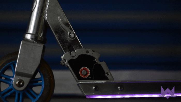
When mounting the magnet to a wheel, it is important to locate in such a way that it is close to the Hall Effect Sensor as the wheel rotates. A stronger tape such as duct tape will usually do the job for this, as can be seen with the black tape below:

Each application of this project will have hardware mounted in its own unique way depending on the layout of the scooter or bike you are mounting to. It is important to house the electronics in such a way to avoid dirt, dust, and water from getting into the electronics.
Double-sided tape and a few zip ties will work fine for this project. The primary concern is making sure that voltage and ground connections do not short on the frame of the scooter or bike. A vulnerable place for this to happen is on the underside of the TinyDuino where both voltage and ground pads are present. Do not put this side of the board directly on the frame. Place electrical tape across these terminals to avoid damaging the electronics.
Another concern is making sure the Hall Effect Wireling is secure enough such that it will not fall off or get caught in the spokes of the wheel.
Contact Us
As always, if you have any questions or feedback, feel free to email us at info@tinycircuits.com.
Show us what you make by tagging @TinyCircuits on Instagram, Twitter, or Facebook so we can feature it!
Thanks for making with us!