TinyHoverCraft Tutorial
Overview
In this tutorial, we will build a small hovercraft that you can control with just a TV remote. By using a few boards and some household supplies, we will create a vehicle that can traverse any flat terrain, even water!
Materials:

- TinyDuino Processor
- Dual Motor TinyShield
- USB TinyShield
- ProtoBoard TinyShield
- Lithium Ion Polymer Battery (3.7V, 270 mAh)
- Any TV Remote or other 38 KHz Infrared Emitter
- Styrofoam bowl, plate, tray, or other dish with hollow space
- Small Paper Plate or Card Stock Folder
- 6mm Counter-Clockwise Motor (2)
- 6mm Clockwise Motor (1)
- Small RC Quadcopter Counter-Clockwise Rotor (2)
- Small RC QuadCopter Clockwise Rotor (1)
- Male Motor Connectors (2)
- Female Motor Connectors (3)
- Small Servo Motor
- Infrared Receiver
- Plastic Bag
- Paper Clip
- Some Balsa or Bass wood (preferably Bass)
- Hot Glue Gun
- Razor Blade
- Soldering Iron
- Tape
Step One: Build the Frame


We first need to measure the rotors and cut holes in the bottom of the styrofoam bowl to allow air to flow in. Flip the bowl upside down (with the opening on the table). Start by drawing two circles with a marker that have the same diameter as each of the rotors. Try to draw the circles as close to the opposite edges of the bowl with relation to each other as possible. Make sure the center line of each of the circles is also the center line of the bottom of the styrofoam bowl.
Take a razor blade and cut out the two holes you just drew, and sand any rough edges. Make sure your rotors could rotate freely in each of the holes.
Step Two: Identify the Motor Placements

Look at the rotors you plan to mount on each of the motors. Can they be mounted only from one side, or are they reversible? In this tutorial, we mount the motors INSIDE of the bowl, but if you use a shallower dish like a plate or tray, or if your rotors can only be mounted from a certain direction, that may not be an option. It is optimal to have the rotors flush with the surface of the bowl, so identify if you need to have the motors mounted on top of the bowl or within it.
Note: Having a lower center of gravity will make the hovercraft easier to maneuver, so mounting the motors inside of the bowl may be ideal.
Step Three: Solder Motors

Take some wire and a motor connector and wire one of the counter-clockwise motors in parallel with the clockwise motor, with the connection terminating at the motor connector. Wrap the connections made in heat shrink tube or electrical tape.
Attach opposite spinning rotors to the two motors that have just been connected.

Note: Make sure you use enough wire to span the distance from the center of each of the holes in the styrofoam bowl. Using too much wire, however, will add unnecessary weight and could tangle the hovercraft.
Step Four: Build Center Motor Mount

Take your basswood and cut a strip of it (3-6mm thick) with the grain about the diameter of the bowl in length. Sand the ends of the basswood strip until they are flush with the center line inside of the bowl. Take your motors and hold them so the rotors are flush with the flat side of the bowl. Observe how far down in the bowl you will need to connect this piece of basswood, and also note how far off the center this beam has to be attached (we want the motors in the center, not the wood connector). Once you have marked the bowl with the gluing positions and have sanded the wood to make a snug fit, hot glue the basswood beam inside the bowl (or on top of the flat side if you are mounting the motors on top of the bowl).
Step Five: Glue Motors

Hot glue the motors connected in parallel to the wooden beam you just inserted. Make sure the rotors are level with each other and flush with the two holes in the bowl.
Step Six: Prep the Boards
If the three female motor connectors have not yet been soldered to the Dual Motor TinyShield, connect these female pins to the pre-soldered ports for motor 1, motor 2, and battery.

Next, connect the ProtoBoard and servo motor. Connect the data line to pin 4, the voltage line to pin VCC, and the ground line to pin GND. Make sure you use a long enough wire to span from one edge of the styrofoam bowl to the other.
After connecting the servo motor, connect the Infrared Receiver to the ProtoBoard as well. Solder the data line to pin 11, the voltage line to pin VCC(the voltage line of the servo will already be there; this is ok), and the ground line to pin GND.


Clip off any extra solder or wire that pierced below the ProtoBoard, and sand smooth. Bend the Infrared Receiver so that it is oriented with the receiver pointed up and the flat side of the module pointing down towards the ProtoBoard.
Step Seven: Assemble the Boards

Stack the Dual Motor TinyShield on top of the TinyDuino Processor. Then place the USB TinyShield on top of the Dual Motor. Finally, place the ProtoBoard with the IR Receiver and the servo on top of the USB TinyShield. Make sure the switch on the TinyDuino is off, and connect the battery to the battery terminal on the Dual Motor TinyShield. Wrap the wire of the battery underneath the board stack, and allow the stack to sit on top of the battery.
Step Eight: Prep the Drive Motor

Solder the last male motor connector onto the one remaining motor. Place the rotor on the motor so that the dominant direction of the rotor (likely the pull direction) is pointing towards the motor. This will likely mean you should place the rotor upside down, but you can always change this later if we guess wrong.
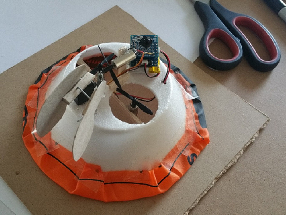
Step Nine: Assemble the Hovercraft Part 1
Place the board stack on the bowl so that it would not impede the rotors from spinning (give yourself a few mm of space, remember you will have wires being plugged in. Try to make sure the switch on the TinyDuino or the battery connector is facing towards the outer edge of the bowl. Tape the stack to the bowl with a piece of double sided tape. (Do not glue! You may want to move the boards for ballast and center of gravity related problems later!)
Use a razor blade to cut a small hole next to the board stack. Run the wires used to connect the two motors wired in parallel through the hole and plug in to the Motor 1 port on the Dual Motor TinyShield.
Use some of the leftover bass wood and create a small motor mount for the last motor. The basswood frame needs to fit between the two rotors flush with the bowl's bottom, and it must be high enough so the rotor that will drive the hovercraft clears rotors and other components below it. Hot glue the motor into place as shown. Connect the male motor connector to the female connector port labeled Motor 2 on the Dual Motor TinyShield.


Step Ten: Assemble the Hovercraft Part 2
Place the servo on the opposite end of the board stack and slightly off center. Hot Glue it in place. This servo will control your rudders.
Take the paperclip and bend it into a straight line. Then bend the paperclip again so about 1 to 1.5 cm (3/8 to 5/8 of an inch) makes a 90 degree angle with the rest of the paperclip. Use wire cutters and cut the paperclip on the long side leaving you with a right angle with a short side of 1 to 1.5 cm and a long side of about 5 cm (or two inches).


Take a short strip of basswood of about 2 cm in length, and glue it to the top of the rotating blade of the servo motor. Measure the distance between the bottom of the basswood and the top of the styrofoam bowl. Place a piece of tape and wrap it around the paperclip angle you just made the same distance up the long side away from the short side. Take another piece of basswood about 2 cm in length and carefully pierce the long side of the paperclip through the end of the basswood strip and slide it down to the tape on the paperclip. Apply another piece of tape to the paperclip just above where the basswood strip now rests.
Hot glue the short side of the paperclip to the styrofoam bowl so that the long end points up and is located in the mid section of one of the blades of the driving rotor. The rotating blade of the servo should be centered in the mid section of the other blade on the driving rotor as pictured.
Connect these two pieces of basswood by taking another piece of paperclip and carefully bending two right angles on it. Use both of the angles to piece through the mid section of both of the basswood strips to create a rotating hinge between the two wooden pieces.


Then take your card stock paper and cut two small rudders out of them in any aerodynamic shape you please. Hot glue each of them to one of the basswood strips so that they are both placed in the center of one of the rotor blades of the driving motor.

Step Eleven: Assemble the Skirt
Take your plastic bag and cut a circle out of it that is about 1.5 to 2 inches greater in diameter than the diameter of the opening in your bowl (the larger end). Use a razor blade or scissors to cut out this circle.

Then measure the distance between the farthest edge of each of the two motor holes in the flat side of the bowl. Cut another circle in the plastic bag out of the circle you just cut. Make sure this circle has the same diameter as the length you just measured and is centered. The result should be a plastic bag washer with a ring width of about three quarters to a full inch.

Place the bowls opening over the plastic bag doughnut and wrap the edges around the bowl and tape down. The skirt is now complete.
Step Twelve: Programming
Plug in the hovercraft to the USB port on your computer and upload the following sketch to the hovercraft.
Almost Done! Setting up the Remote
For this hovercraft, you can use any remote control you want that utilizes Infrared technology. This would include most TV, stereo, media streaming, and other universal remotes.
However, each remote will issue different commands, so before you can control the hovercraft, we need to identify which commands will be needed for the hovercraft.
In the sketch that we uploaded to the hovercraft, the controls are tailored for a certain type of 2nd gen Apple remotes. In order to use any other kind of remote, simply un-comment the line of code that reads, // My_Decoder.DumpResults();
Then turn on the hovercraft and upload this new code to it. Leave the hovercraft plugged in, and open the serial monitor shown below. Make sure the correct COM port is selected and the Speed should be set to 9600. Then just press buttons on your remote and notice the values that come in. You can then tailor the command variable in your code to be receptive to values on your remote. The controls of the hovercraft are clearly labeled in the comments of the code, so you just need to change the values of the remote commands.
Testing

After establishing your command values and editing them into the sketch, re-upload the program to the hovercraft. Once the hovercraft is done updating, point your remote at the IR Receiver and hit one of the buttons you selected to move the hovercraft. If everything is correct, you will see the vehicle operating!
There are other values you may need to change to improve the performance of your hovercraft depending on how you constructed it. Altering the the servoRight, servoLeft, and servoMiddle values will greatly affect steering. Increasing the hoverPower and drivePower variables will let your hovercraft carry more weight and travel faster, but it is worth noting that doing this may cause your hovercraft to be more difficult to control and may reduce battery life.
If you have balance issues, try adding small amounts of ballast to parts of the hovercraft that are floating higher than the rest. You want a nice, level hover.
Have fun testing, and send us videos of all the cool hovercrafts you make! Thanks