TinyLily Motor Board
TinyLily Motor Board quarter size comparison
TinyLily Motor Board back view
TinyLily Motor Board

TinyLily Motor Board

ASL2001

2 in stock
Regular price $ 4.95 Save $ -4.95

OR

When TI came out with the world’s smallest DC motor driver chip, we knew we had to build a board around it. Based around the 2mm x 2mm TI DRV8837 Motor Driver (H-Bridge) IC, this board is incredibly tiny at only 10mm in diameter, yet can drive a 5V 500mA motor!  (Note: Although the DRV8837 is rated at 11V at 1.8Amps, with the small size and small heatsinking, we do not recommend exceeding 5V at 500mA). 

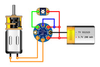
The DRV8837 is extremely easy to use and interface to your favorite processor board (such as a TinyDuino, TinyLily or a standard Arduino), and uses a simple PWM to control motor speed, direction, coasting and braking. The board includes a bypass capacitors and all the I/O of the DRV8837 brought out to sewtabs, as well as heatsinking the chip to a large plane on the bottom side of the board to help with heat dissipation.

The TI DRV8837 has one H-bridge driver consisting of N-channel power MOSFETs to drive a DC motor or one winding of a stepper motor, or other devices like solenoids. An internal charge pump generates needed gate-drive voltages. There are internal shutdown functions for overcurrent protection, short-circuit protection, undervoltage lockout and over temperature. The DRV8837 can supply up to 1.8 A of output current. It operates on a motor power-supply voltage from 1.8 V to 11 V, and a device power-supply voltage of 1.8 V to 7 V. There is also a extremely low power sleep mode with 120nA sleep current.

  • Washable
  • Eight Sewtabs – 1.2mm in diameter, easy to use with standard conductive thread and needles
  • Robust Gold Finish – makes soldering easy and is non-corrosive

    TI DRV8837 H-bridge Motor Driver Specs

    • Low MOSFET On-Resistance: HS + LS 280mOhm
    • 1.8A Max Drive Current
    • 1.8V to 11V Motor Operating Supply Voltage Range
    • Seperate Motor and Logic Power Supply Pins
    • PWM (IN/IN) Interface
    • Dedicated Sleep Pin

    Pins Used

    • VM - Motor Voltage Input:  This supplies the voltage to the motor and can range from 1.8 to 11 Volts (high current connection)
    • GND - Ground: This is the Ground return and needs to connect to the Ground for both the VM supply and the VCC supply (high current connection)
    • VCC - Logic Voltage Input: This is the logic voltage input, and needs to be the same voltage as the system driving the motor controller (like the TinyLily Mini or a standard Arduino).  This will be 3 to 5 Volts if connected to an Arduino based systems (like the TinyLily Mini or the TinyDuino), although the full possible voltage range is from 1.8 to 7 Volts.
    • SLP - Sleep Input: This signal can put the motor controller into a low-power “Sleep Mode”.  A logic-low “0″ will put the motor controller into sleep mode, a logic-high “1″ will put the motor controller into normal operating mode. If sleep mode is not needed, connect SLP to VCC to allow normal operation. NOTE: This must be connected in order for the motor controller to work
    • IN1 - Input 1: This signal controls the Output 1 driver. A logic-low “0″ will set Output 1 to low, a logic-high “1″ will set Output 1 to high. If left unconnected, this signal is pulled down to a low-logic “0″ with an internal resistor.
    • IN2 - Input 2: This signal controls the Output 2 driver. A logic-low “0″ will set Output 2 to low, a logic-high “1″ will set Output 2 to high. If left unconnected, this signal is pulled down to a low-logic “0″ with an internal resistor.
    • O1 - Output 1: This is the Output 1 driver and connects to on2 side of the motor winding (high current connection.
    • O2 - Output 2: This is the Output 2 driver and connects to on2 side of the motor winding (high current connection.
    Dimensions
      • Dimensions: 10mm diameter (0.394 inches)
      • Max Height: 1.41mm (0.056 inches)
      • Ultra-thin 0.61mm (0.024 inches) PCB
      • Weight: .13 grams (0.0046 ounces)
      • Even though the motor driver can support 11V at 1.8Amps, we do not recommend using more than a 5V motor at 500mA due to the small size.  
      • Be sure that your power supply is sufficient to operate these motors as well as your logic – batteries are the best. If you are running both the motors and the logic off of one power supply, we recommend avoid using a switching power supply as the transients caused can potentially damage items connected to the logic side.
      • Although conductive thread can be used for all the connections, for the motor and power connections it is highly recommended to use normal copper wire soldered into these connections due to the power levels involved. If conductive thread is used for these connections, keep these thread lengths as short as possible.