Arduino Star Tracker
This project follows the system design for making a laser-pointer point to a star with a given date, time, GPS location, and the star's celestial coordinates.
Background
The system is calibrated at startup by pointing the laser at the North Star and getting an initial heading and pitch reading from a 9-axis sensor. This initial reading is then used to calculate an offset for both heading and pitch such that the motors will be able to adjust the position of the laser to the specific target horizontal coordinate of a star.
One obstacle in developing this system is the fact that a star's horizontal coordinate is constantly changing as time progresses. Luckily, the equatorial coordinate system uses fixed coordinates for stars which can be converted to the horizontal coordinates we want to use. This way we can predefine coordinates for stars within the program and use the GPS location, date, and time to get real-time updates for the target's horizontal coordinates which we can point to with the aid of the 9-axis sensor.
When the system boots, a GPS reading is taken to get the latitude and longitude of the device. The GPS also gives us the current time and date which is used to initialize the processor's real-time clock (RTC) module. These readings are needed in order to arrive at your local sidereal time (LST). Where one solar day is 24 hours and based around how long it takes Earth to revolve once around its axis, a sidereal day is roughly 4 minutes shorter than a solar day and is based around how long it takes for the Earth to rotate about its axis relative to the stars - this difference is caused by Earth's orbit around the sun. Local sidereal time is needed to get a star's equatorial coordinates based on the system's location.
Let's try to visualize both the horizontal and equatorial coordinate systems.
Horizontal Coordinates

Source: https://en.wikipedia.org/wiki/Azimuth
This is the system we ultimately will use to find our target in the sky. Horizontal coordinates use an azimuth, the direction of a celestial object from the observer, and an altitude to describe the position of a target. The azimuth is the right-hand angle offset from the target to true North. The altitude is the angle at which the target is in relation to the horizon, where the position directly overhead (the zenith point) is 90°. Because this system is oriented in relation to a Northward position, it can easily be calibrated about the North Star, Polaris. It is also important that the system is level to the horizon as well so the altitude is consistent.
Equatorial Coordinates

https://en.wikipedia.org/wiki/Right_ascension
The equatorial coordinate system is a fixed coordinate system meaning the coordinates don't change as time progresses. Equatorial coordinates consist of an angle of declination and an angle of right ascension. Declination is simply the angle of the target from the Earth's equator. Right ascension is the angle between the vernal equinox point and the target. Although the angle of right ascension remains fixed, as Earth rotates, this angle is perceived to be different. We overcome this problem by using the local sidereal time. By subtracting the angle of right ascension from the local sidereal time (in degrees), we arrive at an hour angle which we can use to locate the target at the current local sidereal time. This is a little complicated, but due to the nature of this fixed coordinate system, it allows us to have coordinates pre-programmed which we can then convert to usable horizontal coordinates based on the GPS location and current time.
If you would like to read more on these systems and possibly get a better explanation, check out this article on converting right ascension and declination to altitude and azimuth. You can also read this Wikipedia page on celestial coordinate systems.
Website tools for working with star coordinates:
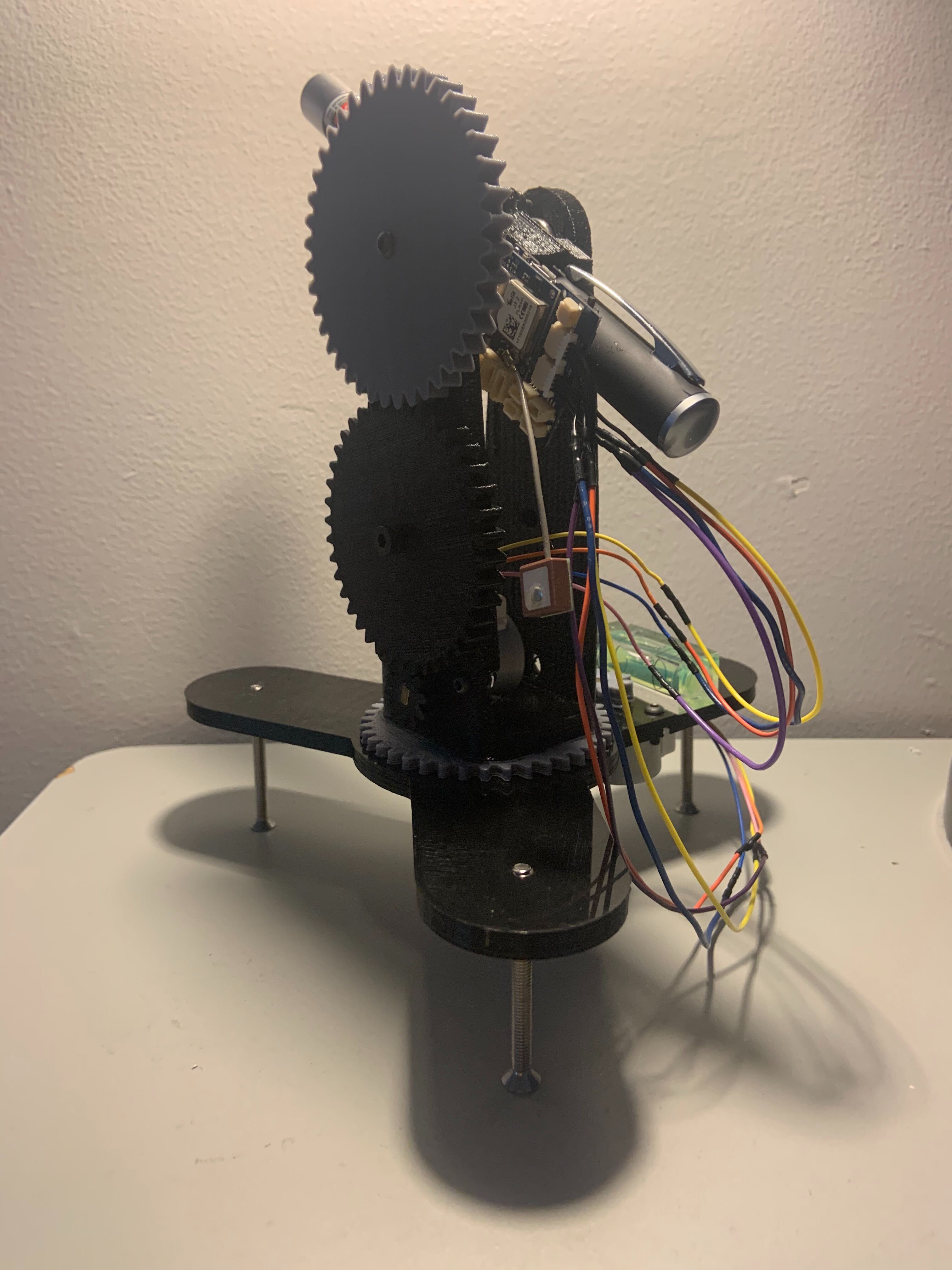
Hardware Assembly
Stack the GPS TinyShield on top of the RobotZero using the 32-pin connector. The onboard 9-axis sensor on the RobotZero will be used to get pitch and heading readings.
A mount is needed to hold and adjust the laser altitude and azimuth after the system is calibrated. STL files are available for the mount shown here, however, the materials you have available to you may change how you go about this step. The code will function so long as your mount has a means of adjusting the altitude and azimuth of the laser. There is a tolerance for both altitude and azimuth which you can adjust in the code if your hardware mount is more crudely constructed. Be mindful that changing the setup may result in a need to change motor direction within the goToAzimuth and goToAltitude functions.
Note the positioning of the RobotZero on our mount. This is important for the 9-axis readings being used by the system, so you should orient your RobotZero in the same fashion in relation to your laser.
Notes on the Laser/Hardware Mount
- the laser mount is designed such that two M3 bolts can thread directly into the holes on the side and grip a 15mm diameter laser
- the laser mount is designed such that two M1 bolts (the bolts featured in the TinyDuino Mounting Kit) can thread directly into the mount to hold the RoborZero processor in place
- the bolt holding the top gear to the laser mount should be tightened so the rotation of the gear caused by driving the declination motor will cause the pitch of the laser to change
- both motors are secured by two M3 bolts and two M3 nuts each
- longer M4 bolts are to be used on the base so they can be adjusted to level the system
- due to the size of the system, the motor cables will have to be extended so they're able to reach the processor board
Software Setup
The GPS module will automatically get the latitude, longitude, and UTC time needed for the functionality of this project. However, if you know where you are setting up the system and would like to have a manual input of this data at startup, the system will still function as long as these values are accurate. This means this project can still be built without a GPS TinyShield, but it will require a little more additional programming and setup time.
Upload Program
Plug in the micro USB cable from your computer to the RobotZero. Make the appropriate tools selections in the Arduino IDE and upload the program to the RobotZero.
This project is set up to be used alongside a laptop to interface with the system outdoors. After the program is uploaded, it is important to level the system such that the laser can point accurately. Once the system is leveled, plug the RobotZero into the laptop and align the laser onto the North Star, Polaris. After the laser is fixed on the North Star, open up the serial monitor. This will calibrate the system and the system can then locate a star given its coordinates by using the pitch and heading readings from the 9-axis sensor.